Fish Wiggle Effect in Unity using Shader Graph
One of the most important aspect in a video games is animations. Animations make objects more interesting, draw player attention, and can be an indicator that the object is a living thing.
The common way of creating animations (especially for 3D objects) is to create bone representation of the object and control them over a period of time to do some kind of movements. The animation can then be saved, exported and then played at will, however the animation itself will occupy extra memory.
While it is absolutely fine to do that, simpler animations can be replicated procedurally without having to manually create the animation. The way to do that is using shader to control each vertex position of the object. Since it is done by shader, all calculations will be done by GPU which makes it more performant. Another benefit of using shader is that you can expose many parameters to control the animation, so using the same shader you can create many different animation variants. That being said though, it is generally more difficult to write shader to replicate the animation than to manually create the animation itself.
In this tutorial, we are going to attempt to replicate wiggling fish animation using shader. Imagine you are trying to make an this animation for 100 different fish. Since the fundamental movement of the animation is basically the same, you can use this same shader to make 100 different animation variants instead of manually creating 100 different animations. This GIF below shows the final result.
The model I used for this tutorial can be downloaded here. The full source code for this project is available at SteveImmanuel/unity-fish-wiggle.
Before we start, this tutorial assumes you have the following requirements:
- Basic understanding of Unity
- Basic understanding of Shader
- Basic knowledge of linear algebra
Project Setup
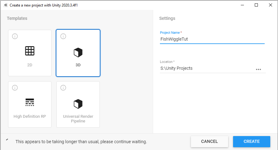
Let’s create a new Unity project. We are going to use Universal Render Pipeline (URP) for this project, so you can choose the URP template or use the 3D template and then upgrade it later on once you are inside Unity.
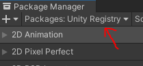
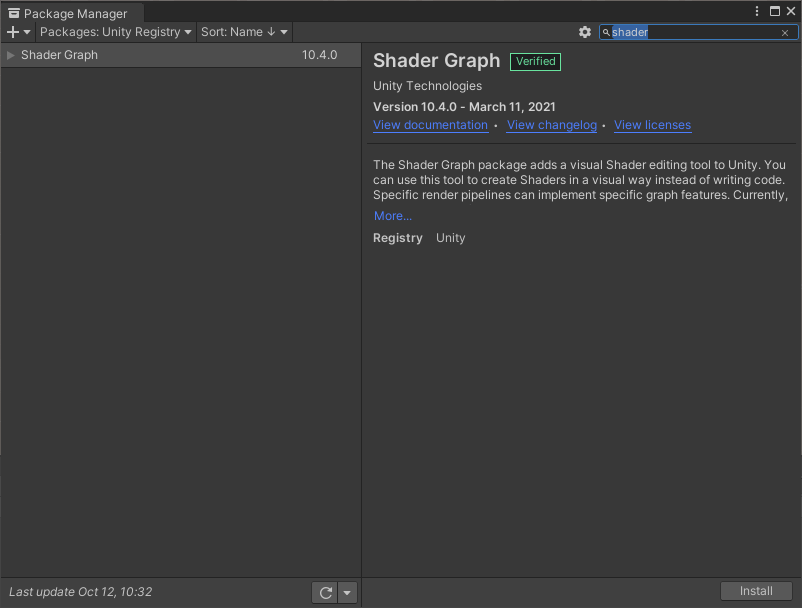
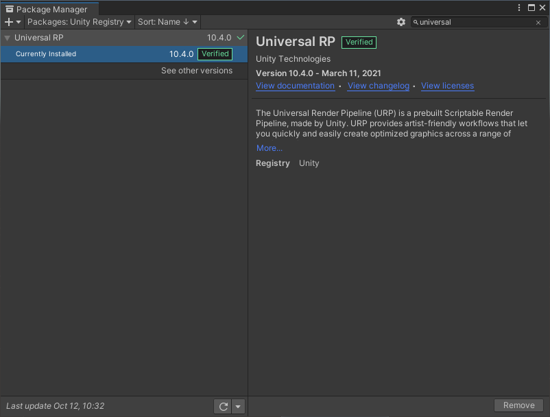
Next, we need to download the Shader Graph package from the Package Manager (Window->Package Manager). If you can’t find it, make sure to choose the Unity Registry from the drop down menu.
Make sure these two packages are installed.
Scene Setup
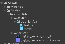
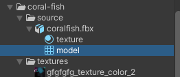
Now, let’s import the fish model into Unity. Extract the files and then simply drag them to the asset folder of the Unity project. Leave the import setting as default. The result will look like the following.
Drag the coralfish.fbx into your scene and the fish model should pop right up like so.
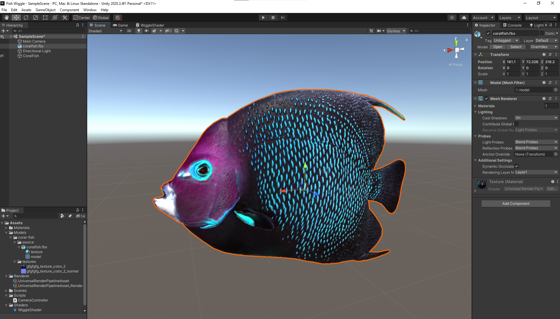
If you encounter a problem where you have a pink-colored object, I recommend you check my other tutorial on the Scene Setup section to address this issue.
Wiggle Shader
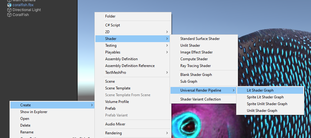
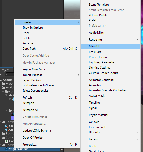
Create a Lit Shader Graph from the URP as shown in the picture below. Let’s name it WiggleShader.
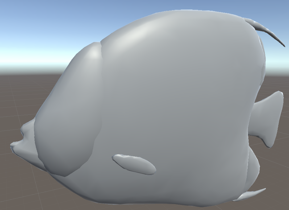
Then, create a new material from that shader and name it WiggleMat. Assign the material to the fish model and it should look like this.
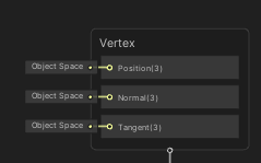
In this shader, the main focus is in the Vertex part, especially the Position output. That output lets us control where each vertices of the object will be rendered in the screen. We are going to manipulate the positions over time to create the animation.
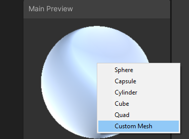
In the Main Preview window (located on the bottom right corner of the shader graph editor), you can use custom mesh and select the fish model in order to better visualize the result of the shader.
This shader consists of 2 main modules which are texture map and wiggle effect.
Note: If you’re having a hard time understanding what a node does, you can always refer to the Official Documentation.
Texture Map
Right off the bat you can see that our fish now missing all of its texture and looks grey-ish. To fix it, we need to create property to control the textures that the model uses. The model that we used provide us with base map (which is the base color for each part of the fish) and normal map (which will provide additional details of the surface in regards to lighting).
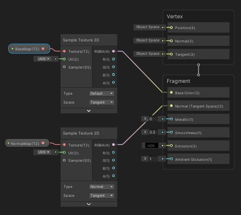
Create two Texture2D property and name it BaseMap and NormalMap. Next, connect the each property to the Sample Texture 2D node. Change the type of Sample Texture 2D to Normal for the NormalMap property. This is very important because normal map requires additional calculation in order to work properly.
Connect the RGBA output from the BaseMap to Base Color and the RGBA output from the NormalMap to the Normal output.
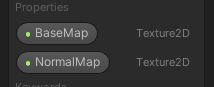
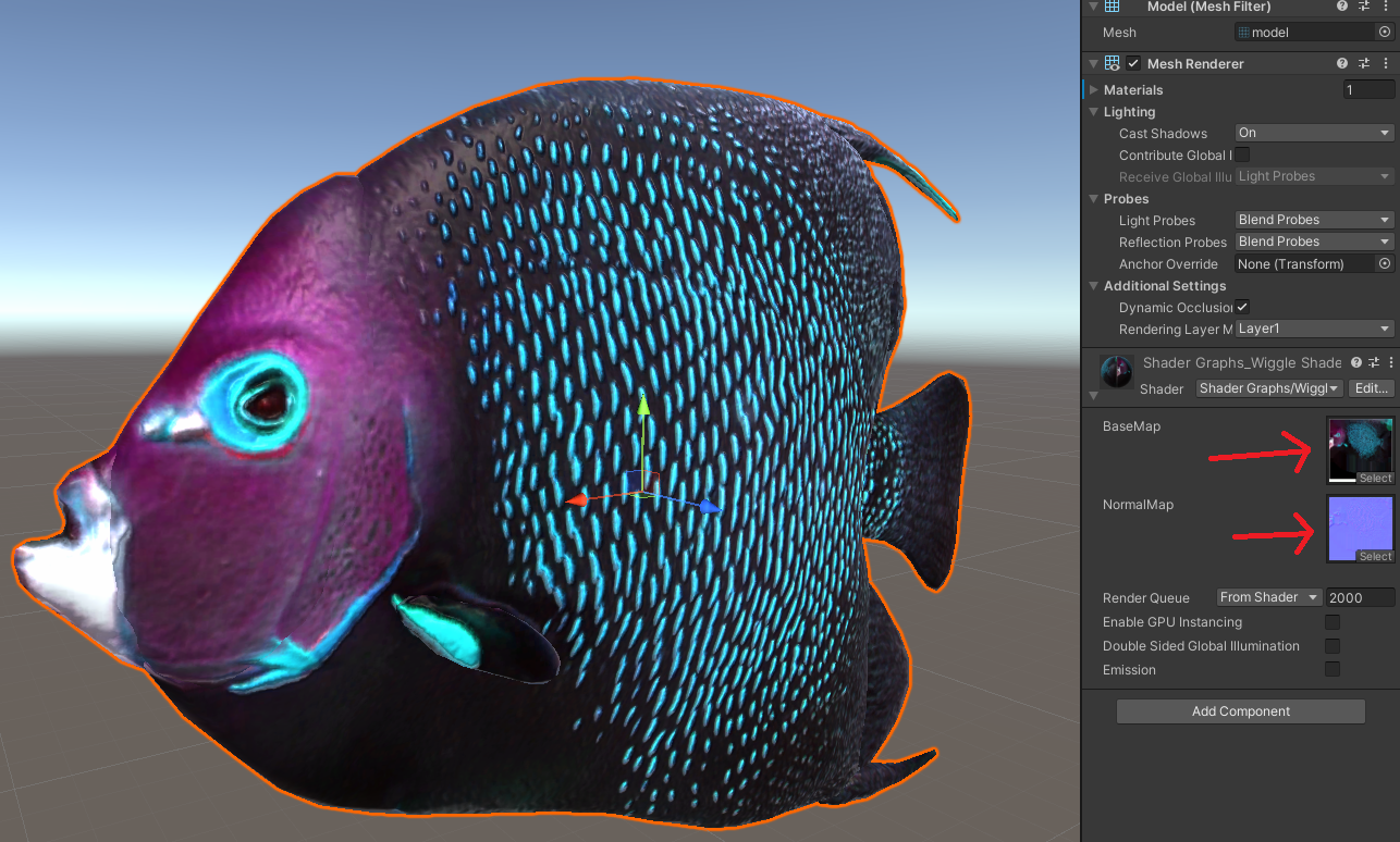
Save the shader, go back to the material properties in the inspector and set the BaseMap and NormalMap accordingly. Now, your fish should look like the one in the beginning when you just imported the model.
Wiggle Effect
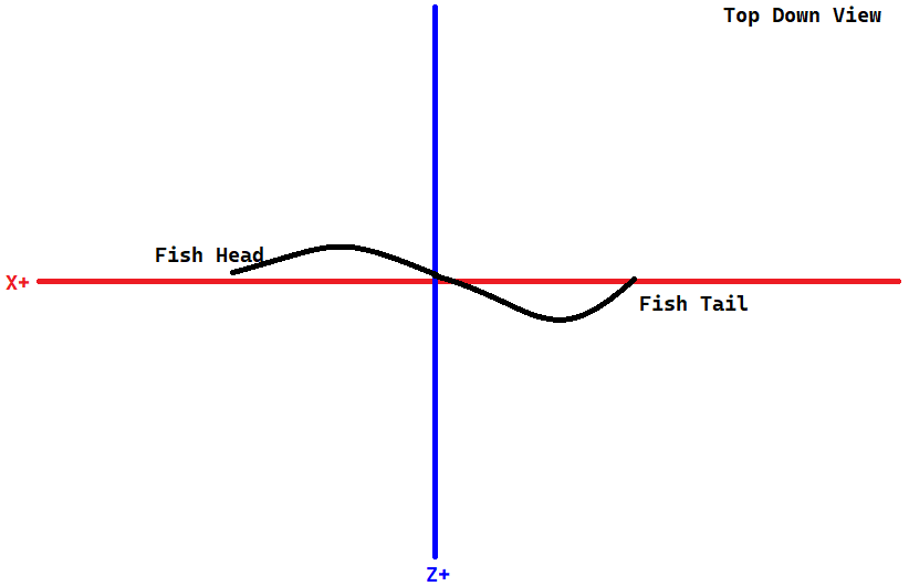
In order to understand how this shader works, you need to look at axes of the fish model first. Notice that the fish head is pointing toward X positive axis which means we want to create wiggle along this axis. Each vertex of the object is consist of x, y, z position information. We need to modify the z value of each vertex. In other words, we need to manipulate the z value of each vertex based on the x value.
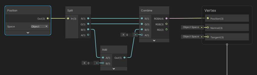
First, create Position node and set it to Object Space, then use Split node to get the position information for each axis. Use the Add node for the B output (which represents z axis) from the Split node to add some value. We will control this value, for now let’s leave it as default. Now, combine everything back using Combine node and connect the output to the Position input of Vertex.
Now if you try to increase/decrease the value on the Add node you should see that the fish will move along the z axis. However, the whole fish will move altogether like some kind of offset in z axis. We don’t want that, what we want is to move in z axis by different amount based on the x value.
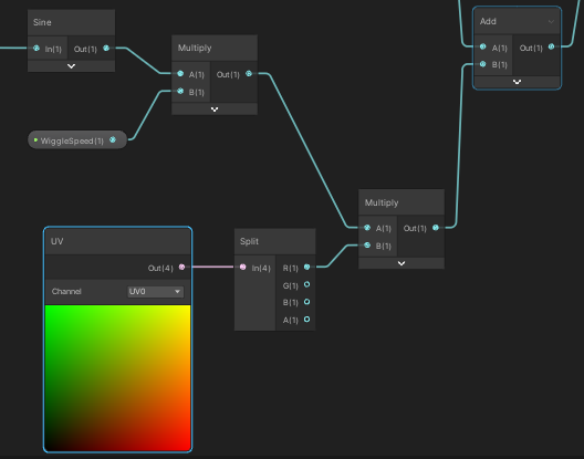
To simulate the wiggle effect, I’m going to use sine wave. In order to simulate the animation, we need to use a value that changes overtime. In shader, we can use the Time node for exactly that purpose.
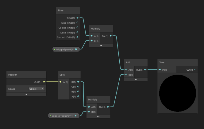
Create 3 float properties and name it WiggleSpeed, WiggleFrequency, and WiggleAmplitude. Create Time node, multiply the Time output with WiggleSpeed. Next, create Position node in Object Space, get the x value using Split node and multiply it by WiggleFrequency.
Note: If you try to preview to each output from the Split node using Preview node, you will see a ball with color gradient from black to white. To better comprehend it, imagine you are looking at a ball from Z- axis, the X axis goes from left to right, and the y axis goes from bottom to top. The values goes from -0.5 to +0.5 in the preview, however it is actually based on the real position that you see in the Scene window.
What I’m trying to say is that in the x preview, the leftmost part of the ball does not represent the vertex located in the most negative x axis but it represents the vertex that is located exactly in -0.5 in x axis. This also applies for other axes as well.
Combine the output from previous nodes with Add node and connect it to Sine node.
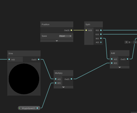
Multiply the output of Sine node with WiggleAmplitude. This series of operation represents the value that we are trying to add to z axis based on x value of each vertex. So, now connect the output to the Add node that we created earlier.
Now, if you save the shader, and tweak the parameter you will have a working wiggle effect on your fish. I find the best parameter for this model to be 0.07 and 3.33 for the WiggleFrequency and WiggleAmplitude respectively.
Don’t go too crazy on the WiggleFrequency because you might end up with something like this if you set it too high. This happens because the z value changes drammatically for a small x different and the model doesn’t consist of that many vertices.
Note: Notice the orange outline in the GIF above. As you can see, the actual model actually stays in place. What we are modifying is actually just the position where each vertices will be rendered.
Now, let’s take care of final small thing. If you look closely, the head part of the fish wiggles as much as the rest of the body. When you look at fish anatomy, you should see that fish head consist of mainly bones so it could not wiggle as much.
We need to limit the amount of wiggle based on the x value. In the figure below, the red line represent the wiggle that we made, while the blue line represent the limit we are trying to make. What we want is the combination of both lines where the value of the red line cannot exceed the value of the blue line.
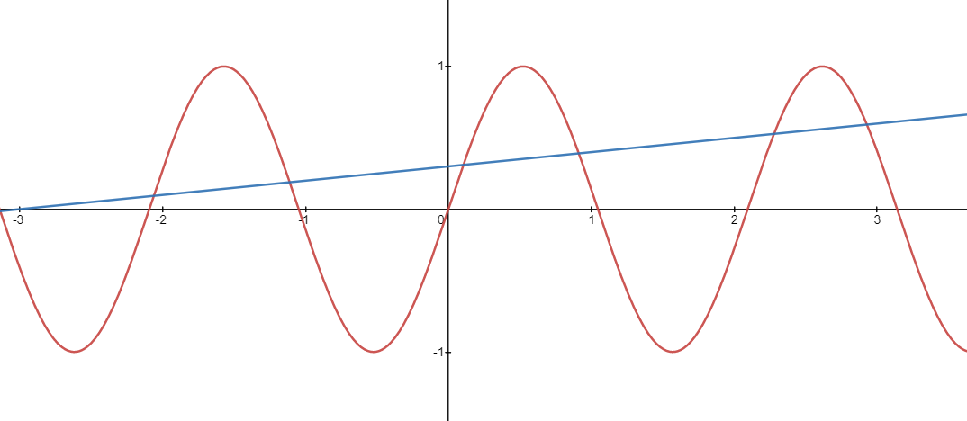
In order to create that limit, we can use some kind of gradient that goes from 0 to 1 and multiply it with the output of our Sine node. To get this gradient, we can use the model UV map. To inspect the model UV, select the model mesh and view the UV layout from the inspector as shown below.
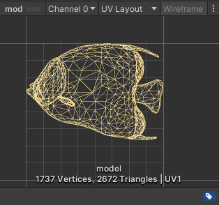
To comprehend UV map, imagine that the 3D model is unwrapped unto square 2D plane. This 2D plane is the UV map. The coordinate system for UV map goes from (0, 0) on bottom left to (1, 1) on top right.
Notice that the fish head is located in the left part, while the tail is on the right part. So, we can use the x value of the UV map as the mask for our sine wave.
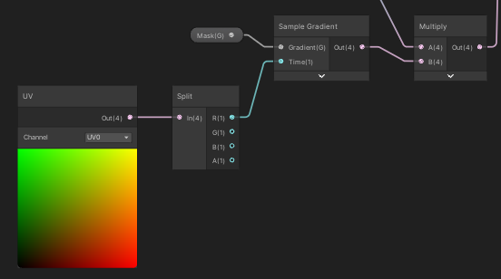
Create UV node and split it to get the x value. Next, multiply it with the output of Sine node and connect to the result to the Add node.
Note: The color preview from the UV node represents the coordinate using in R, G format. So (0, 0) is black, (0, 1) is green, (1, 0) is red, and so on.
Now, save the shader and you will see that the head will not wiggle as much as the rest of the body. If you think that the head still wiggles to much, you can create a Gradient property and sample it using the UV x value and use it as a mask instead. That way you can control the gradient of the mask itself.
Play around with the properties in the material inspector and you can create many different animations. For example, you can control the WiggleSpeed through C# script to indicate the movement speed.
Conclusion
In this tutorial we learn how to fish wiggle animation using shader in Unity using Shader Graph. The animation is created by modifying each vertex position over time.